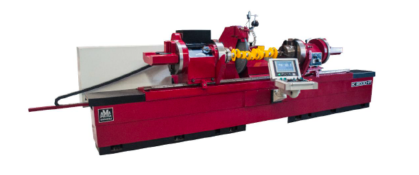
K-20000P Crankshaft Grinding Machine
Capacity: 2250 mm (89")
Swing over table: 690 mm (27")
Stroke: twice off-set of centres 280 mm (11")
Colour: red Graduation: mm or inch
CRANKSHAFT GRINDING MACHINE MODEL K-2000P
1 electric installation for 400 volts, 3 phase AC, 50 cycles
1 grinding wheel motor 5.5 kW
1 electric motor for hydraulic power station 1.1 kW
1 coolant pump 0.12 kW
1 crank centering V-gauge with dial indicator
1 set-up indicator with dial gauge
1 steady rest, standard
1 wheel dresser for face and side dressing
1 wheel dresser for radius dressing
1 diamond tipped dressing tool, 0.75 ct.
1 grinding wheel 813 mm (32") x 203.2 mm (8") x 25 mm (1")
1 grinding wheel hub with balancing arbor
1 lifting hook for grinding wheels
1 complete coolant arrangement with tank, hoses and nozzles
1 set of splash guards and spanners
1 operating manual and spare parts catalogue
DESCRIPTION OF THE MACHINE WITH STANDARD EQUIPMENT:
BED
One piece cast iron
Alignment by means of a number of adjusting screws
Guide ways protected by guards
TABLE
Surface with 10Åã inclination
Guide ways with antifriction coating
Guide ways lubrication with lubricate rollers and oil pocket fed from an oil pump
Rack and pinion gear for head- and tailstock movement
Movements performed by means of SKF 50 mm (1.97”) ball screw with pre-loaded ball nut.
Movement performed by means of a SIEMENS 1FL6+V90PN servomotor 2,5 kW (11.9 NM)
Speed 5 to 4000 mm/min. (0.2”-197”)
HEADSTOCK
Rigid spindle with . 170 mm (6.7”) SKF NN-double row bearing
Movement performed by means of a SIEMENS 1FL6+V90PN servo motor 2,5 kW (11.9 NM) and connect
with a gear, digital converter system, range 5-100 rpm.
Setting-up system comprising two throw heads with 190 mm (7.") chucks
(indexing for every 30Åã and 72Åã) incl. jaws with 254 mm capacity, ball screw for throw head movement
Index pins, manual operated
1 Packing for shipping
15 Price list no. 165
TAILSTOCK
Rotating spindle with . 170 mm (6.7”) SKF NN double row bearing
setting-up system comprising two throw heads with 190 mm (7.") chucks
incl. jaws with 254 mm capacity, one centre with back plate, ball screw for throw head movement.
70 mm (2.7”) hydraulically operated quill, adjustable centre pressure
Side adjustment Å} 2 mm, controlled by a 40 mm (1.57”) dial gauge
Locking pin for non-rotation of spindle for working with centres
WHEELSLIDE
Guide ways with antifriction coating
Guide ways lubrication fed from an oil pump
Movement performed by means of 40 mm (1.57”) SKF ball screw with pre-loaded ball nut
with SIEMENS servo motor drive 1FK7+S120 3,3 kW 10.5 NM.
Speed 5 to 3000 mm/min. (0.2”-118”)
GRINDING WHEEL HEAD
Hardened spindle runs in the grinding wheel end in a tapered adjustable and hand scraped
sleeved bronze bearing of heavy duty design
At pulley end pre-loaded high precision angle contact bearings are used
The grinding spindle is driven by AC motor, and as option with variable speed 500-800 rpm.
GRINDING WHEEL GUARD
Grinding wheel guard for protection of the 813 mm (32”) grinding wheel with a max.
width of 63.5 mm (2,5”)
GRINDING WHEEL HUB
A grinding wheel hub 12" (305 mm) dia. with clamping width 19 – 63.5 mm (0.75” – 2.5”)
3 pcs. adjustable balancing arbours
Rapid wheel change system
ELECTRICAL SYSTEM
Detached relay box
Cabinet for power supply 400 volts 3 phase, 50 cycles
24 volt DC for control of circuits
Plug-in relays with thermal overload protection
Built-in ventilation for cooling of electrical equipment
CONTROL
The machine has a CPU1511 for control, X, Z and C-axes
AMC operator panel with SIMATIC HMI Touch operated 9” TFT colour display
The machine can be used in manual mode, and also have a semi auto function where it is possible
put in some parameter for a start position in X, and end position in X, and how much for fine grinding,
feed for rough- and for fine grinding, the X axis stop when reach the end position, and it is possible
move the Z axis if the width of journal is more than the width of grinding wheel.
It also have an auto function where it is possible put in some parameter for a start position in X, and
end position in X, and how much for fine grinding, feed for rough- and for fine grinding, dwell time
when reach end position in X, and when the dwell time run out the X axis will move back.
As an option it is possible connect the AEM (AMC ELECTRONIC IN PROCESS GAUGING) to the
PLC so it handle when the machine go from rough to fine grinding and when start the dwell and final
position.
There is also a cycles for cylindrical grinding, where put in some parameter for turn position right and
left side, the speed in Z axis and dwell time in both end.
For B2B customers, please register here for EU VAT exemption.