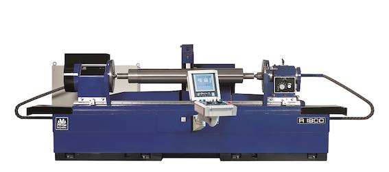
R-1400 Precision Cylindrical Grinding Machine PLC Controles
R-1400 Precision Cylindrical Grinding Machine PLC Controles
(Image may differ from actual product)
|
SPECIFICATIONS: |
||
|
Maximum workpiece length: |
1400 mm |
(55,1”) |
|
Maximum workpiece diameter: |
460 mm |
(18") |
|
Maximum grinding diameter: |
420 mm |
(16.5”) |
|
Maximum workpiece weight between centers: |
200 kg |
(441 lbs) |
|
Maximum workpiece weight between chucks: |
300 kg |
(661 lbs) |
|
Power supply: |
3 x 400 V, 50 cycles + 0 cable |
|
|
Colour: |
Blue RAL 5013 |
|
|
Graduation: |
mm or inch |
|
BED |
|
One piece cast iron |
|
Alignment by means of a number of adjusting screws |
|
Guideways protected by telescopic guards |
|
TABLE |
|
Surface with 10° inclination |
|
Guideways with antifriction coating |
|
Rack and pinion gear for head- and tailstock movement |
|
Movements performed by means of SKF 40 mm (1.57”) ball screw with pre-loaded ball nut. |
|
Movement performed by means of a SIEMENS 1FL6+V90PN servomotor 1,75 kW (8.36 NM) |
|
Speed 5 to 3000 mm/min. (0.2”-118”) |
|
Guide ways lubrication with lubricate rollers and oil pocket fed from an oil pump |
|
HEADSTOCK |
|
Rigid spindle with Ø 100 mm (4.0”) SKF angle bearing. |
|
Movement performed by means of a SIEMENS 1FL6+V90PN servo motor 2,5 kW (11.9 NM) |
|
digital converter system, range 5-500 rpm. |
|
Hub prepared for fitting chuck. |
|
Morse Taper No. 4 hole in the spindle for centers. |
|
TAILSTOCK |
|
Rotating spindle with Ø 100 mm (4.0”) SKF angle bearing |
|
Hub prepared for fitting chuck |
|
50 mm (2”) hydraulically operated quill, adjustable centre pressure. |
|
Side adjustment ±2 mm, controlled by a 40 mm (1.57”) dial gauge |
|
Locking pin for non-rotation of spindle for working with centres |
|
Morse Taper No. 4 hole in the spindle for dead or live centres |
|
WHEELSLIDE |
|
Guideways with antifriction coating |
|
Guideways lubrication fed from a pump |
|
Movement performed by means of 40 mm (1.57”) SKF ball screw with pre-loaded ball nut |
|
with SIEMENS servo motor drive 1FK7+S120 2,1 kW (8 NM). |
|
Speed 5 to 2000 mm/min. (0.2”-78”) |
|
GRINDING WHEEL HEAD |
|
Hardened spindle runs in the grinding wheel end in a tapered adjustable and hand scraped |
|
sleeved bronze bearing of heavy duty design |
|
At pulley end pre-loaded high precision angle contact bearings are used |
|
The grinding spindle is driven by a 5,5 kW AC-motor with variable speed, maximum 1,000 rpm. |
|
GRINDING WHEEL GUARD |
|
Grinding wheel guard for protection of the 660 mm (26”) grinding wheel with a max. |
|
width of 50 mm (2”) |
|
GRINDING WHEEL HUB |
|
A grinding wheel hub 8" (203.2 mm) dia. with clamping width 19 – 50 mm (0.75” – 2”) |
|
3 pcs. adjustable balancing arbors |
|
Rapid wheel change system |
|
CONTROL |
|
The machine has a CPU1511 for control, X, Z and C-axes |
|
AMC operator panel with SIMATIC HMI Touch operated 9” TFT colour display |
|
The machine can be used in manual mode, and also have a semi auto function where it is possible |
|
put in some parameter. |
|
There is two different way: |
|
Manuel infeed. |
|
There must be set 4 parameter from the screen: |
|
a. Position z-axis right side |
|
b. Position z-axis left side |
|
c. The speed mm./min. the z-axis should move. |
|
d. Number of seconds that must dwell in the ends (Example 10) |
|
Automatic infeed: |
|
There must be set 15 parameter from the screen: |
|
a. Position z-axis right side |
|
b. Position z-axis left side |
|
c. Start diameter (example 142.512) |
|
d. Final diameter (example 142.000) |
|
e. Grinding rough (how much should be grind per time in diameter, example 0.060) |
|
f. Grinding fine (how much should be grind per time in diameter, example 0.003) |
|
g. Number of fine cut (Example 5) |
|
h. Number spark out (Example 2) |
|
i. Speed workpiece rough grinding |
|
j. Speed workpiece fine grinding |
|
k. Speed workpiece spark out |
|
l. Z-axis speed rough grinding |
|
m. Z-axis speed fine grinding |
|
n. Z-axis speed spark out |
|
o. Number of seconds that must dwell in the ends (Example 10) |
|
ELECTRICAL SYSTEM |
|
Detached relay box |
|
Cabinet for power supply 400 volts 3 phase, 50 cycles |
|
24 volt DC for control of circuits |
|
Plug-in relays with thermal overload protection |
|
Built-in ventilation for cooling of electrical equipment |
|
TOOLS |
|
1 grinding wheel balancing arbor |
|
1 puller for change of grinding wheel |
|
1 set of tools, spanners. |
|
1 lifting hook for grinding wheels |
|
LITERATURE |
|
1 Operating manual with spare part section |
|
1 Packing list |
|
|
For B2B customers, please register here for EU VAT exemption.